
IoT is an advanced technology for monitoring or
controlling the electronics systems by using the internet as a medium. Nowadays we
are searching for a medium that can be easily available for all users as well as
has a wide range of coverage. The Internet is one of the media which is available for almost every person and it has a wide range of coverage even over the seas. Here
we are going to discuss the simplest IOT project where we will use nodemcu
which is a microcontroller board with a built-in esp8266 Wi-Fi interface and control an LED using a button and get its status on the LCD screen. For
controlling our microcontroller based system we will use an android application
named “Blynk”.
So let’s start setting up our Blynk app.
Blynk:
Nodemcu is a microcontroller board with built-in Wi-Fi.
Nodemcu board can be programmed using Arduino ide and for that, we have to just
download libraries for nodemcu and add preferences but we are not going to
discuss how to setup nodemcu, here we are going to discuss how to setup
Blynk. For adding libraries for Blynk follow the following step –
1.
Open Arduino ide
2.
Sketch
3.
Include library
4.
Manage libraries
5.
Search for Blynk
6.
Install the first result

Now Install the Blynk app from the play store on your mobile and
open it. At first, you have to login, in this, you have to give an email id in
which the authentication key will be sent. This key is very essential for
linking your app to your project.
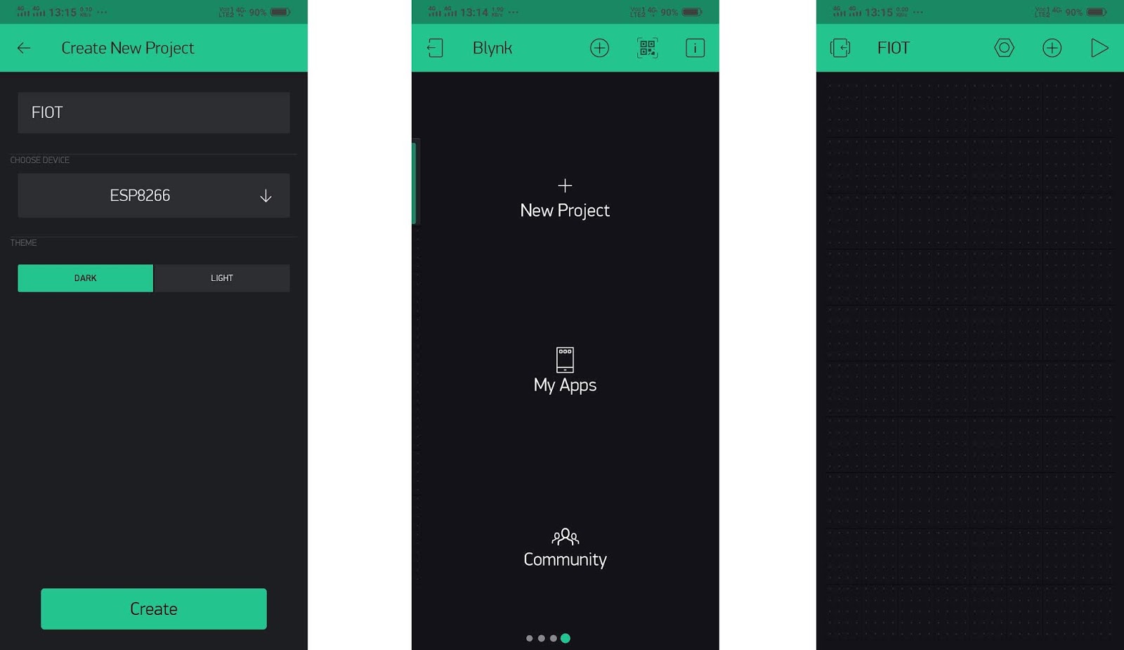
After login, you have to create a new project by pressing +
sign (New Project) button. Then you have to give a name to your project and select
the board like it is raspberry pi, esp8266, or any other IoT boards. Here we are
going to use esp8266 so select it. After that click on the create button. Now we
will get a message regarding to authentication key which is sent to the registered email-id. After that this we will get an empty project and now we can add various widgets in this empty
project like buttons, sliders, LCD display LED, etc.
For adding those we have to tap on + sign at the upper right corner and you will get all the things that we need in the current project and here we are going to add an LCD screen and a button for controlling the led. After choosing the widgets (LCD or button) tap on it and here you can configure it for LCD screen toggle the LCD control type simple to advance after that LCD requires only one pin (virtual) for controlling it and in this project select virtual pin 1 (V1). Now move on the button, tap on the button, and set digital pin gp5 as output pin actually, all digital and analog pins chosen in the app give output at respective gpio pin on board.

Here all the settings of our app are completed now we can
move on to our board programming section. The programming section is very simple, first
of all, we have to put authentication key which was sent on registered email-id,
after that give to internet access by giving SSID (Wi-Fi name) and password. Here
we are using serial communication for getting information about the connection
status of the board whether it is connected to the internet or not and it is optional.
Now in the setup section first of all clear the LCD screen and put the initial
values (status of led). In the loop section we continuously monitor the button
status and send the status on LCD. Here we are using if-else because we want to
print the led status only one time for one status (on or off) otherwise it won’t
print properly because of the loop and very high refresh rate. Flash the program on your nodemcu board and in the app tap the play button located at the top right corner and wait for the successful internet connection, you can monitor the connection using serial monitor of the Arduino IDE if your board is connected to the computer by USB cable. After successful connection your first IoT project ready for test!!
here is the code for this project:-
#define BLYNK_PRINT Serial
#include <ESP8266WiFi.h>
#include <BlynkSimpleEsp8266.h>
WidgetLCD lcd(V1);
int status1 = 0;
int x = 0; //flag for current led status
char auth[] = "Auth Key"; // your authentication key from mail
char ssid[] = "SSID"; // your wifi name
char pass[] = "PASSWORD"; //your wifi password
void setup()
{
// for checking connection
Serial.begin(9600);
Blynk.begin(auth, ssid, pass);
lcd.clear();
lcd.print(0, 0, "Electroitsum");
lcd.print(0, 1, "LED: OFF");
}
void loop()
{
Blynk.run();
status1 = digitalRead(D1); // read pin status
if(status1 == HIGH){ //for led on
if(x == 0){
lcd.clear();
lcd.print(0, 0, "Electroitsum");
// (position X: 0-15, position Y: 0-1, "Message you want to print")
lcd.print(0, 1, "LED: ON");
delay(10);
x = 1;
}
}
else{
if(x == 1){ //for led of
lcd.clear();
// (position X: 0-15, position Y: 0-1, "Message you want to print")
lcd.print(0, 0, "Electroitsum");
lcd.print(0, 1, "LED: OFF");
delay(10);
x = 0;
}
}
}
--------------------------------------------------------------------------------------------------------------------------
Output:-


No comments:
Post a Comment